Atreus build part 3: Wiring up the switches
This post belongs to the Atreus build series, which was introduced by Onward with the Atreus keyboard.
Last night I started soldering the rows and columns. The rows are connected by diodes (to avoid a bounce back effect from residual current on key up) while the columns are simply wired together. This multiplexing allows us to only need as many digital inputs as there are columns and rows (11 + 4, the middle thumb keys are in a column of their own).
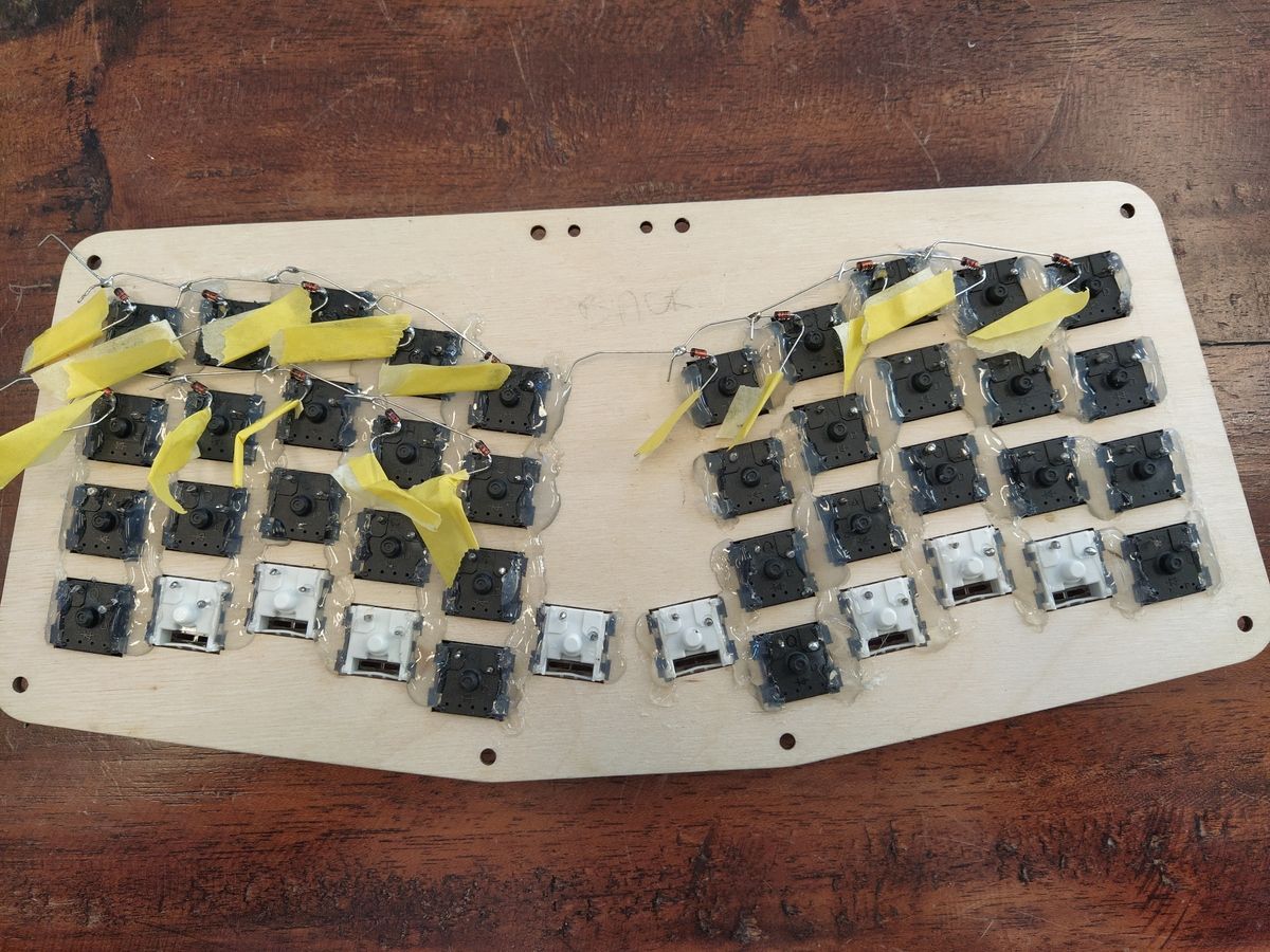
Soldering the diodes to the left pin and connecting them in parallel(!), row by row.
I wanted to have an easy time (visually) tracing the columns so I mirrored the wire colours along the vertical middle axis. Satisfying to look at.
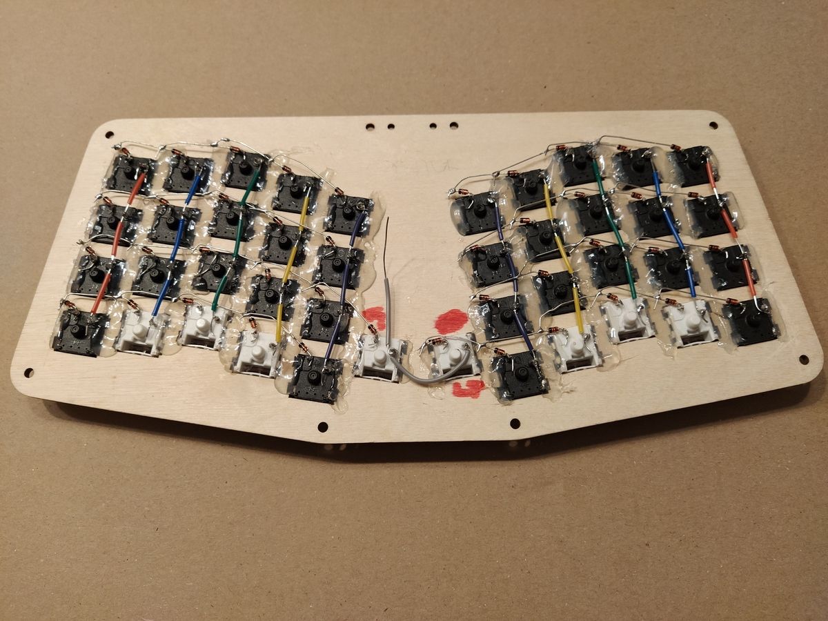
Each column connects four switches together, by their right pin. The inner most column only has two switches in it.
Once all the switches are wired and ready to be connected to the micro-controller, I really realised how a tight fit it would be. Best to wire the Pro Micro upfront to then solder the long loose wires to the rows and columns.
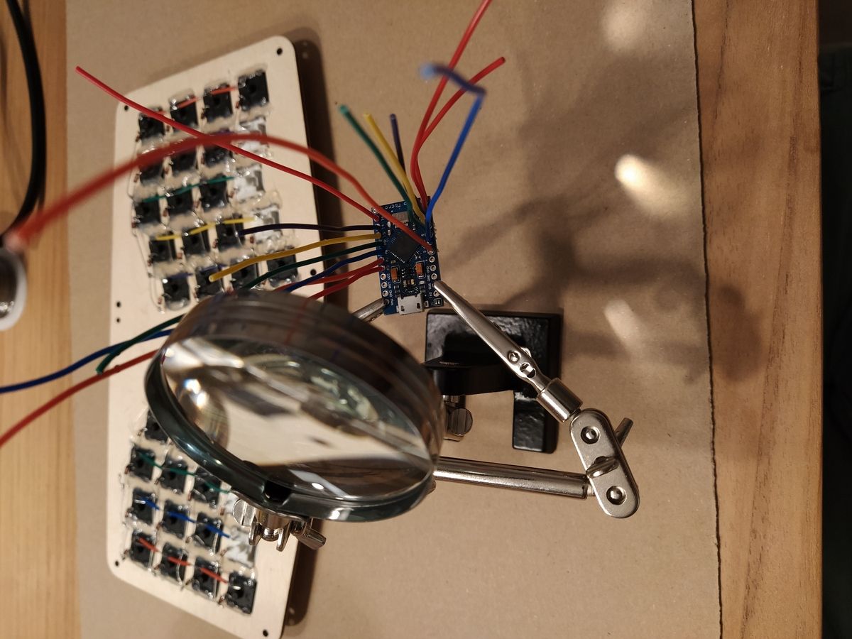
Each digital input/output is soldered to a piece of wire beforehand.
To keep the standard mapping of columns to digital I/O expected by the firmware, I used the same colour coding for the loose wires. Then it’s simply about soldering wires by colour.
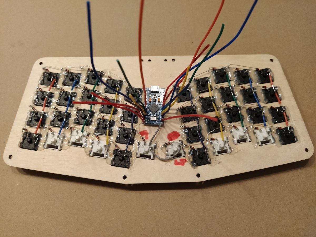
Getting ready to solder all rows and columns to the micro-controller.
I finished soldering early morning and then went to bed, satisfied with my good work (or so I thought). I was surprised to realise only half of the keyboard was registering key presses this morning. I forgot to connect both ends of each row, duh.
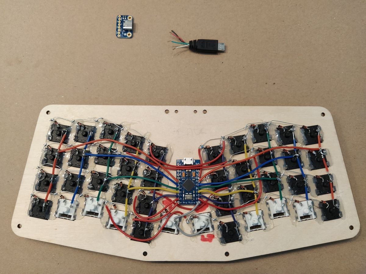
Final look after soldering the micro-controller. The micro-controller is only secured with the soldered wires, no additional hot glue. The USB-C breakout board will come next.
I now have a fully functional 42-key keyboard! But it’s connected with a non-detachable (because inside the case) micro-B USB cable. Next up: soldering the USB-C breakout board to a loose male micro-B cable and fitting it in the case.